 |
|
|
Development of the
Construction of Roadbed
I decided to lay down a concrete base (or roadbed) as I had done on my first garden in California. This
involves some risk because the winters are cold in Central Oklahoma and
the red clay soil is very expansive. Many local sidewalks and streets are
broken and buckled. I decided to take the chance (or do the required
maintenance and replacement). I made this choice because the wind, rain,
and hail can be severe and can move the track around if it is not secured.
I will need to remove leaves in fall and snow in winter; a track secured
to a firm roadbed will be easier to clean. Also, I wanted to elevate the
track a little above grade, and raising the roadbed on fill-dirt would add
instability to the base. 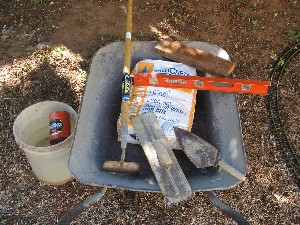
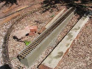
I elevated the base about 6 inches above ground level for the first section. This will elevate the entire railway above ground level for slightly better viewing. The first section was at the lowest point in the yard. I started with a straight section to give me an easier starting point. 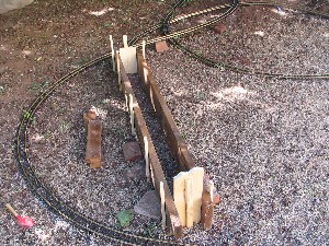 I formed the first pour with 2-by-4’s on each side. The roadbed was made 5.5 inches
wide corresponding to the width of some scrap 1-by-6 lumber. I used
pre-mixed concrete in 60-lb bags.
I formed the first pour with 2-by-4’s on each side. The roadbed was made 5.5 inches
wide corresponding to the width of some scrap 1-by-6 lumber. I used
pre-mixed concrete in 60-lb bags.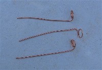 I stripped the
coating off of some #12 copper wire and bent one end into a circle. These
were inserted into the wet concrete to serve as track tie-downs.
I stripped the
coating off of some #12 copper wire and bent one end into a circle. These
were inserted into the wet concrete to serve as track tie-downs.
 I removed
the forms after about 6 hours and roughed up the surface lightly so that
it looks more like soil if exposed. My intent is to cover it with
gravel.
I removed
the forms after about 6 hours and roughed up the surface lightly so that
it looks more like soil if exposed. My intent is to cover it with
gravel.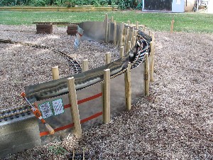 Curved sections were poured using 12-inch wide aluminum “roof-flashing” for
the forms. I first placed 7-8 feet of track firmly together using bricks
to support the height. The boards or flashing were placed alongside this
track. Many stakes were pounded into the ground on the outside of the form to hold
it approximately
in place when the concrete was poured. A piece of wood was placed between
each section of base. This was removed after the concrete set up, leaving
a space between sections for concrete expansion.
Curved sections were poured using 12-inch wide aluminum “roof-flashing” for
the forms. I first placed 7-8 feet of track firmly together using bricks
to support the height. The boards or flashing were placed alongside this
track. Many stakes were pounded into the ground on the outside of the form to hold
it approximately
in place when the concrete was poured. A piece of wood was placed between
each section of base. This was removed after the concrete set up, leaving
a space between sections for concrete expansion.For most sections it was necessary to mix the concrete very dry. This makes mixing more strenuous, but it was necessary because many sections required a grade, and very wet concrete will not hold a grade while working it into place (wet concrete will seek a level surface like water). I used a level with a “wood lifter” at one end to approximate the grade. 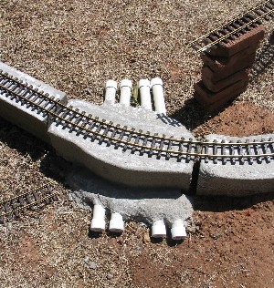 I placed four 1 ½ -inch pvc pipes under the base at several
points for electrical lines, water pipes, drainage, and other unknown
utilities. This diameter of pipe is large enough to fit a ¾-inch pvc
pipe, if necessary.
I placed four 1 ½ -inch pvc pipes under the base at several
points for electrical lines, water pipes, drainage, and other unknown
utilities. This diameter of pipe is large enough to fit a ¾-inch pvc
pipe, if necessary.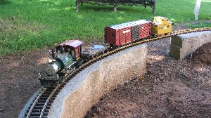 At several locations, I left gaps in the concrete base.
These gaps will be for gullies or roadways going under the track.
Bridges will be built to span the gaps.
At several locations, I left gaps in the concrete base.
These gaps will be for gullies or roadways going under the track.
Bridges will be built to span the gaps.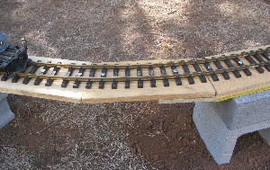 Some of the track base will be trestle. However, the trestles cannot be built
until the fill dirt is in place and the topography is established.
To continue with the construction of the base, I spanned those areas with boards. The photo to the left shows
a close-up of the span construction on a curve, and the photo below shows a
lengthy curved span going to a bridge. The track was secured to the
boards with 1 1/4-inch screws. It is elevated on concrete blocks with some plywood
and/or styrofoam spacers to achieve the desired elevation. This allows me to continue
building the track base until the circuit is complete.
Some of the track base will be trestle. However, the trestles cannot be built
until the fill dirt is in place and the topography is established.
To continue with the construction of the base, I spanned those areas with boards. The photo to the left shows
a close-up of the span construction on a curve, and the photo below shows a
lengthy curved span going to a bridge. The track was secured to the
boards with 1 1/4-inch screws. It is elevated on concrete blocks with some plywood
and/or styrofoam spacers to achieve the desired elevation. This allows me to continue
building the track base until the circuit is complete.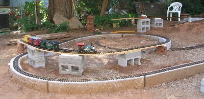
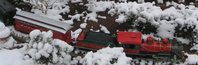
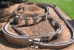
The track is now entirely in place (August 29, 2004). The two photos below show the layout from an aerial view and a ground view. After fill dirt is brought in and the general topography established, the board/concrete block base will be replaced by trestles. Note the triple level crossover on the left of the second photo below. 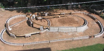
|
Shoppe Foreman is the family website of Larry and Sandy Foreman.
Revised November 2008.